Views: 0 Author: Site Editor Publish Time: 2026-09-22 Origin: Site
Undersized piping creates massive bottlenecks that restrict your entire plant operation. This critical flaw creates excessive pressure drop across your distribution network. This bottleneck forces air compressors to overwork constantly. Energy costs spike rapidly as a result. Meanwhile, your pneumatic equipment starves for the steady power it needs to function properly.
Solving this issue requires meticulous planning and accurate engineering. Proper compressed air pipe sizing balances initial material costs against long-term energy efficiency. Operational reliability also depends heavily on this strategic balance. Failing to respect fluid dynamics inevitably leads to wasted electricity and poor tool performance.
Our objective is straightforward. We aim to provide plant managers and engineers with a rigorous framework. You will learn to evaluate system requirements accurately. You will discover how to calculate exact dimensions for your layout. We also cover how to source reliable infrastructure. Applying these right methods early protects your facility and ensures peak production uptime.
Total allowable pressure drop from the compressor to the furthest point of use should not exceed 5% of the operating pressure.
Determining compressed air pipe diameter requires factoring in system flow rate, operating pressure, total pipe length, and the "equivalent length" of all fittings and valves.
Future-proofing is critical; oversizing main headers slightly today is significantly cheaper than replacing a bottlenecked system in five years.
Material selection (such as smooth-bore aluminum) drastically impacts friction coefficients and long-term sizing accuracy.
Engineering a distribution system is not just about moving air. It revolves around protecting your financial margins. Small miscalculations during the design phase compound into massive utility bills over time.
Pressure drop measures the energy lost to friction as air travels through a network. Every 2 PSI (0.14 bar) of pressure drop equates to roughly a 1% increase in compressor energy consumption. If your pipes are too narrow, internal friction spikes. The compressor pushes harder to compensate for this resistance. This drains your electrical budget rapidly. You pay an invisible premium every hour your compressor runs.
Correct sizing guarantees stable pressure exactly at the point of use. Pneumatic tools demand specific pressure ratings to meet quality and torque standards. Fluctuating pressure ruins product consistency. A sudden drop in air power might cause a torque wrench to under-tighten a critical bolt. Properly sized industrial air piping solves this. It acts as a reliable reservoir, supplying instantaneous power when multiple tools fire simultaneously.
Plant managers often hesitate at the upfront cost of larger pipes. However, they deliver compounded, year-over-year electrical savings. A low-friction system minimizes resistance. You recover the initial capital premium through dramatically lower operating expenses. Investing in properly dimensioned headers now secures future profitability. Undersizing saves a few dollars today but costs thousands in wasted electricity tomorrow.
You cannot simply guess your pipe dimensions based on older facility layouts. Engineering precise routing requires measuring four specific variables accurately.
First, you must establish the maximum demand of your system. Not all machines run simultaneously. You must apply a utilization or diversity factor. Calculating your true peak compressed air flow rate prevents dangerous undersizing. A facility with fifty tools might only use twenty concurrently. Determine this realistic maximum flow before selecting any physical pipe sizes.
Next, identify the most demanding equipment on your production line. What is its lowest acceptable pressure? This target becomes your baseline standard. Every upstream component must support this specific baseline. If a packaging machine requires 90 PSI to function, your compressor must generate enough pressure to deliver 90 PSI at that exact drop, accounting for all friction in between.
Physical straight-line distance only tells half the story. Internal turbulence disrupts airflow significantly.
Elbows: Force air to change direction, creating massive drag.
Tees: Split airflow, inducing colliding pressure waves.
Valves: Restrict passage size, increasing localized friction.
You must translate these turbulent areas into "equivalent lengths" of straight pipe. Add these equivalent lengths to your linear physical pipe distance before calculating the final diameter.
Speed matters immensely in fluid dynamics. Engineering standards dictate keeping air velocity below 20-30 ft/s (6-9 m/s) in main headers. Slower velocities minimize moisture carryover and reduce friction drastically. High velocities strip condensed moisture from traps. The fast air then hurls this water into sensitive downstream tools. Keeping velocity low protects your equipment and ensures smooth delivery.
How do you synthesize these variables into a concrete decision? You follow a disciplined, step-by-step evaluation framework. Transparency in your assumptions guarantees a reliable final layout.
You generally choose between two distinct methods for sizing. Empirical lookup tables (nomograms) offer quick, visual sizing guides. Fluid dynamics equations provide higher mathematical precision. Both are useful depending on the project scope.
Sizing Method Comparison Chart
Evaluation Method | Speed of Use | Precision Level | Best Application |
|---|---|---|---|
Engineering Nomograms | Fast (Visual Lookup) | Moderate (Ranges) | Quick estimations and simple branch sizing. |
Empirical Formulas | Slower (Calculation) | High (Exact metrics) | Complex networks and large main headers. |
Manufacturing facilities rarely remain static. Production lines expand, and demand grows. We highly recommend adding 25-30% to your current peak flow rate assumptions. This strategic buffer accommodates future plant expansions without issue. Sizing strictly for today's needs forces you into a corner. Oversizing slightly now prevents a massively expensive total repipe five years down the road.
You must set a strict pass/fail threshold for your design. A universally accepted standard is allowing a maximum 0.3 bar drop across the entire distribution network. Any proposed compressed air pipe diameter must meet this rigid criteria. Calculate the total drop. If the calculation shows a drop higher than your budget, you must upsize the main header immediately. Do not compromise on this threshold.
Mathematical equations assume a specific friction factor. Your chosen material dictates whether that friction factor remains stable or worsens over the system's lifespan.
Internal surface roughness dictates long-term performance. Black iron and galvanized steel degrade predictably over time. Scaling, moisture, and rust build up inside them. This corrosion creates a rough internal texture. The rough surface dramatically increases pressure drop as years pass. Smooth-bore materials prevent this degradation entirely, locking in your original mathematical calculations.
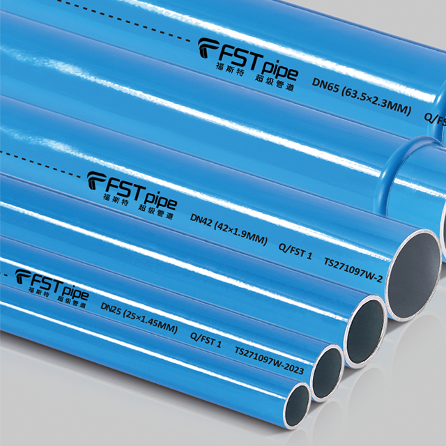
Specifying modern materials secures your investment. For example, installing a DN20-DN200 aluminum pipe network ensures a constant internal diameter. It features a zero-corrosion surface. Your calculated size on day one remains perfectly accurate in year ten. Steel pipes eventually narrow from internal rust, choking off airflow. Aluminum does not rust, scale, or degrade, ensuring consistent energy consumption.
Material weight impacts project timelines heavily. Aluminum is significantly lighter than traditional threaded steel. This lighter profile allows for easier suspension from facility ceilings. It requires less robust mounting hardware. It also facilitates faster modifications. Your maintenance teams can adapt the layout rapidly using simple hand tools, avoiding heavy threading machinery entirely.
Perfect math fails if the physical routing is flawed. Structural geometry and installation best practices dictate final operational performance.
Layout geometry transforms system efficiency. A closed-loop design, commonly called a ring main, effectively halves the pressure drop. Air flows in two distinct directions to reach any point of high demand. This dual-path delivery minimizes velocity spikes. Dead-end lines, conversely, force all air through a single congested path. They create massive friction at the furthest ends of the facility.
Gravity serves as a highly effective moisture separator. You must tap off the top of the main header when routing air downward. These upward-curving risers, often called swan necks, prevent condensation from flowing down into equipment drops. If you tap from the bottom of the header, condensed water flows directly into your pneumatic tools. Swan necks force water to remain in the header until it reaches a dedicated auto-drain.
Even a perfectly calculated main header fails if restricted at the endpoint. Warn your installation teams against common bottleneck risks.
Undersized Flexible Hoses: Small whip hoses restrict massive amounts of flow.
Cheap Quick-Disconnects: Poorly designed fittings create severe internal turbulence.
Restrictive FRLs: Filter-Regulator-Lubricator units must match the flow capacity of the drop.
These small, overlooked components easily negate the benefits of properly sized main piping. Always specify endpoint accessories that match or exceed required flow rates.
Sourcing materials requires vetting your vendors rigorously. A solid procurement partner guarantees project success beyond just delivering boxes of pipes.
Look far beyond basic parts catalogs. A highly credible compressed air piping supplier provides deep technical backing. They offer sizing validation for your proposed plans. They supply accurate equivalent length charts specifically tested for their unique fittings. Excellent vendors also provide layout CAD support to ensure your ring main geometry is structurally sound before installation begins.
Evaluate their warehouse stocking capabilities. Do they stock a comprehensive range of fittings and diameters locally? Full availability of sizes from DN20 to DN200 is crucial for seamless deployment. This deep inventory supports your immediate installation needs without delays. It also guarantees replacement parts and expansion components will be available when your plant grows in the future.
Verify vendor safety certifications directly. Ensure their materials meet ASME, CE, and ISO standard compliance. Industrial pressure systems carry inherent physical risks. You need robust, multi-year warranties against leaks and hidden material defects. Do not accept uncertified, generic piping components under any circumstances. Certifications guarantee the material can withstand decades of continuous pressurization.
Precise pipe sizing is an ongoing asset management strategy, not just a one-time construction task. Proper planning dictates how efficiently your entire plant operates for decades. You ensure predictable energy consumption by prioritizing accurate diameter calculations, utilizing low-friction materials, and designing loop layouts. The initial effort spent evaluating variables easily pays for itself through drastic reductions in compressor electrical costs.
Take action today to optimize your system. Audit your facility's current pressure drop from the compressor room to the furthest machine. Consult with an engineering specialist to validate your upcoming layout. Secure high-quality, zero-corrosion piping to guarantee your airflow remains unrestricted for the lifetime of your facility.
A: Undersized pipes cause excessive air velocity and severe pressure drops. Your compressor must overwork to push air through the restriction, spiking energy costs. High velocities also rip condensed moisture past traps, carrying water directly into sensitive pneumatic tools, which causes internal rusting and decreased equipment lifespan.
A: No. We strictly advise against using PVC. It violates OSHA safety standards for compressed gases. PVC becomes brittle over time and degrades when exposed to compressor oils. When PVC fails under high pressure, it shatters catastrophically, sending dangerous, razor-sharp plastic shrapnel across the facility floor.
A: Higher flow rates demand larger internal pipe areas. If you force a massive volume of air through a narrow pipe, the speed (velocity) increases dramatically. This friction causes severe pressure loss. Upsizing the pipe diameter slows the air down, reducing friction and preserving pressure to the endpoint.
A: It varies heavily by the internal diameter of the pipe. Generally, a single 90-degree elbow can add anywhere from 1 to 5 feet of straight pipe equivalent in friction. You must always consult the manufacturer-specific equivalent length tables for accurate calculations during your layout design phase.